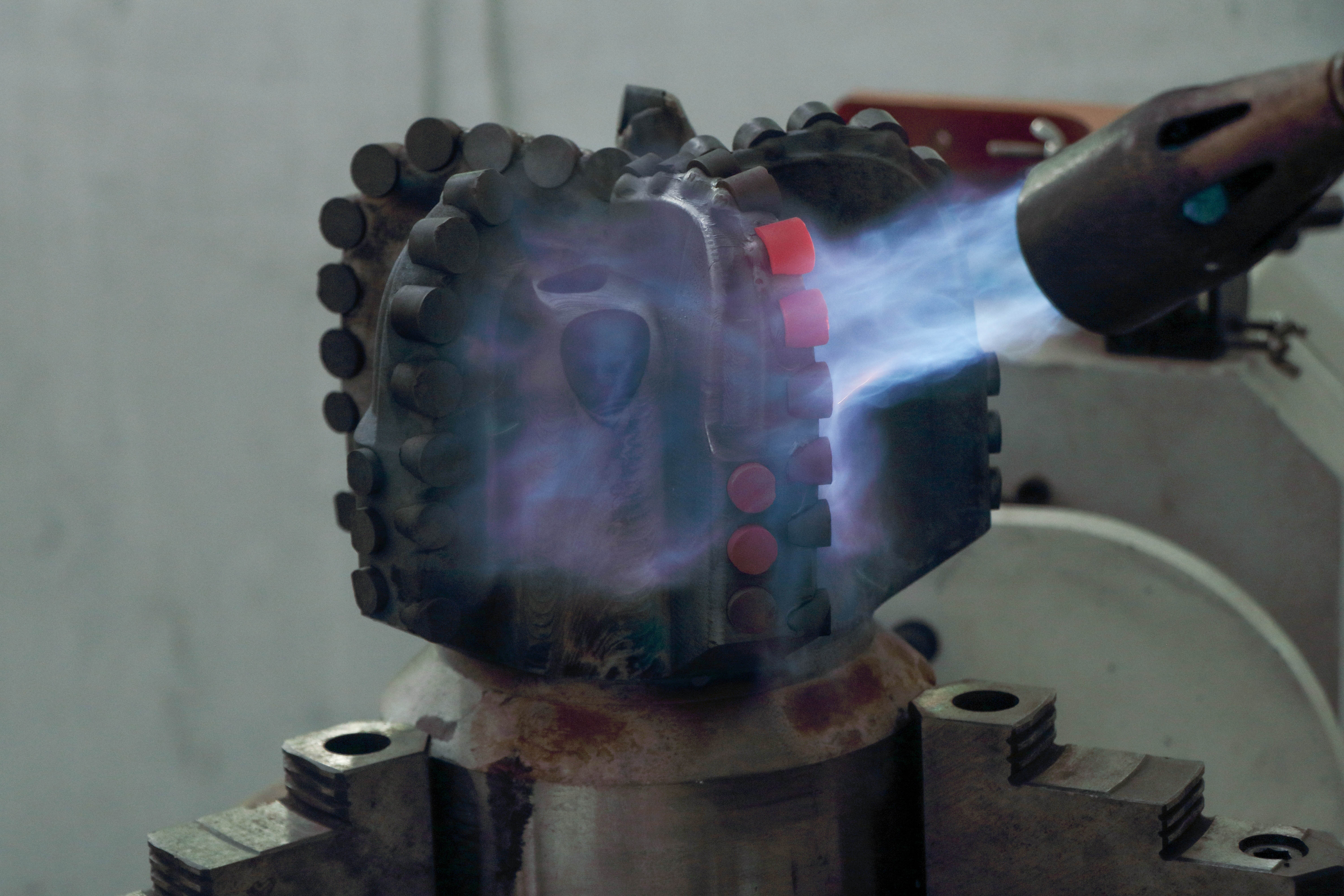
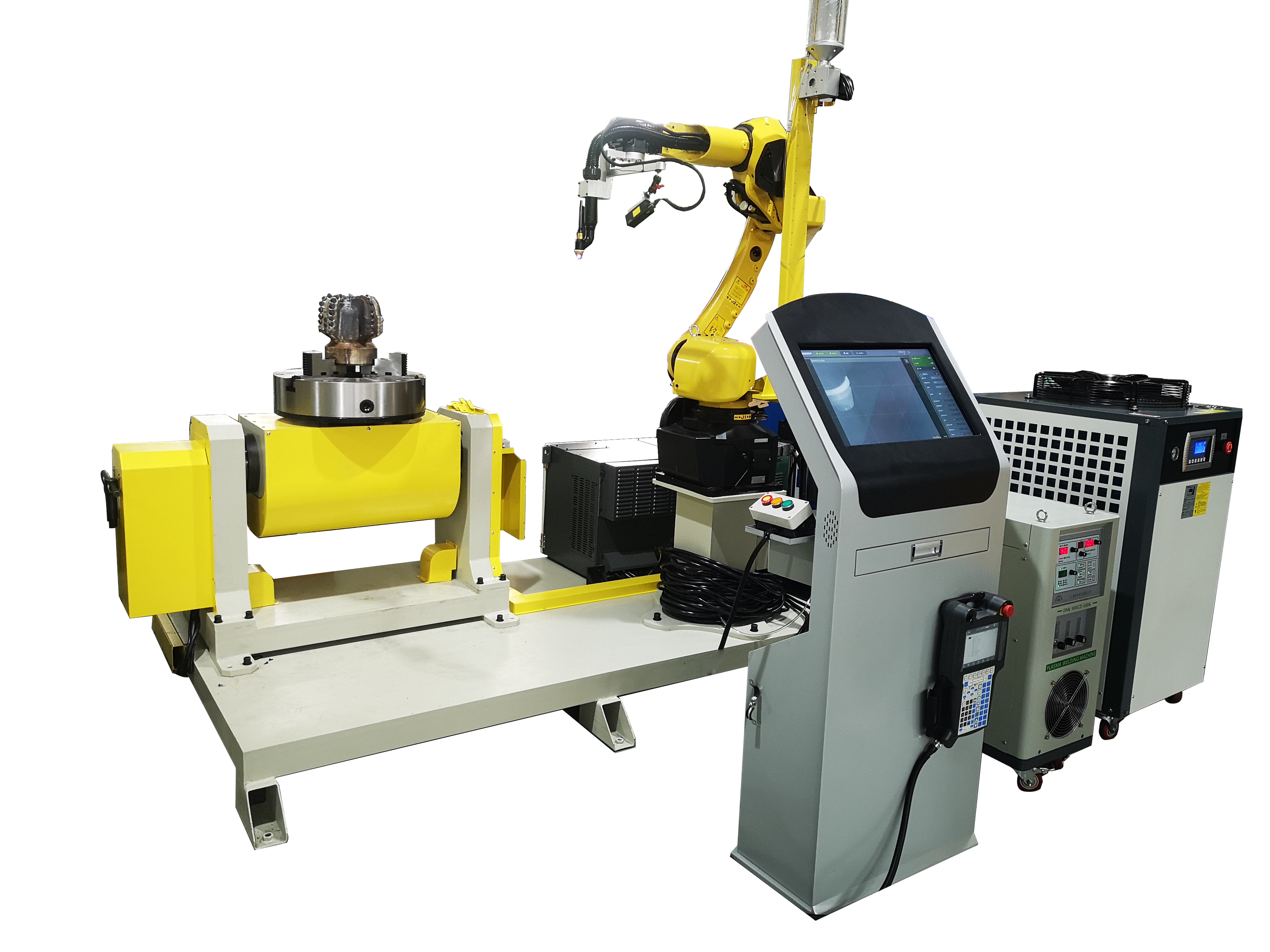
Применение технологии плазменной наплавки для упрочнения поверхности буровых долот PDC является эффективным средством повышения их износостойкости, ударопрочности и коррозионной стойкости.
1. Подготовительный этап

(1) Определить материал облицовки
- Наиболее часто используемые облицовочные материалы:
- Сплав на основе кобальта: высокая износостойкость и коррозионная стойкость.
- Сплав на основе никеля: устойчив к высокотемпературному окислению и химической коррозии.
- Сплавы на основе железа: экономичны и подходят для случаев, когда требуются средние требования к износостойкости.
- Сплавы, армированные керамическими частицами: например, WC (карбид вольфрама), TiC (карбид титана) и т. д., для удовлетворения очень высоких требований к износостойкости.
(2) Определение площади облицовки
- Наплавка буровых долот PDC обычно применяется для:
- Боковая часть: для повышения износостойкости и снижения трения и потерь при резании.
- Поверхность каркаса: для повышения общей коррозионной стойкости и ударопрочности.
(3) Предварительная обработка поверхности
- Очистите область наплавки от масла, окислов, покрытий и загрязнений.
- Механическая шлифовка или пескоструйная обработка для повышения шероховатости поверхности и улучшения сцепления наплавленного слоя облицовки с подложкой.
2. Реализация процесса плакирования
(1) Настройка оборудования для плазменной наплавки
- Состав оборудования:
Плазменный сварочный пистолет, податчик порошка, автоматизированная плазменная сварочная машина, и т. д..

- Задайте ключевые параметры:
- Ток и напряжение дуги: выбираются в зависимости от покрываемого материала, обычно в диапазоне 100-300 А.
- Подача тепла: отрегулируйте для контроля деформации субстрата и скорости разбавления.
- Скорость подачи порошка: обычно в диапазоне 10~50 г/мин для обеспечения равномерности наплавочного слоя.
(2) Выполнение облицовки
- Процесс плакирования:
1. Зажигание плазменной дуги, образование высокотемпературной расплавленной ванны.
2. Через систему подачи порошка порошковый материал распыляется в расплавленную ванну и металлургически связывается с подложкой.
3. в соответствии с формой сверла, по заданной траектории для равномерной наплавки, чтобы гарантировать отсутствие утечки наплавки или переплавления.
- Контроль теплового воздействия: предотвращение перегрева или деформации основания бурового долота PDC путем регулирования параметров плазменной дуги и метода охлаждения.
(3) Охлаждающая обработка
- Естественное охлаждение или применение метода контролируемой скорости охлаждения для предотвращения образования трещин, вызванных термическим напряжением.
3. Этап после лечения
(1) Проверка качества облицовки
- Осмотр внешнего вида: проверьте однородность слоя покрытия, отсутствие трещин и воздушных раковин.
- Эксплуатационные испытания: измерение твердости, толщины (обычно 0,5 ~ 3 мм), прочности сцепления и других показателей.
- Неразрушающий контроль: используйте ультразвуковой или рентгеновский контроль для выявления внутренних дефектов.
(2) Отделка
- Если после наплавки поверхность шероховатая, необходимо провести токарную или шлифовальную обработку, чтобы она соответствовала требованиям к размеру и форме буровых долот PDC.
(3) Оптимизация производительности
- Термическая обработка: при необходимости закалка или отпуск наплавленного слоя оболочки для дальнейшей оптимизации его структурных свойств.
4. Меры предосторожности
1. Избегайте перегрева
- В процессе плазменной наплавки необходимо строго контролировать подвод тепла, чтобы избежать термического повреждения вставки PDC и подложки.
2. Соответствие материалов
- Материал покрытия должен соответствовать материалу подложки долота PDC, чтобы обеспечить прочность соединения и постоянство эксплуатационных характеристик.
3. Экологический контроль
- По возможности в условиях низкой влажности или защитного газа, чтобы избежать окисления, влияющего на качество облицовки.
Этот процесс можно использовать для повышения производительности новых долот PDC, а также для ремонта изношенных долот.
Время публикации: 09 января 2025 г.

